
Floor Groover and Blade Compatibility
Browse This Page
Compatibility Checklist
| Check | What to confirm |
|---|---|
| Identify the Groover and Blade System | Record the exact groover model, serial or revision, order reference and current blade marking. |
| Isolate Before Looking at the Mount | For a powered groover, switch off, wait until all moving parts stop, unplug and follow the manual before accessing the blade. |
| Measure an Electric Disc at Defined Datums | Record outside diameter, central bore, body thickness, stated cutting width and profile, plus any locating holes, slots, spacers or offset. |
| Check Rotation, Rating and Guard Clearance | Use the exact machine instructions to check blade direction, permitted speed or rating, fixing and clearances. |
| Record Hand-Blade Retention Separately | For a hand groover, record blade length, width, thickness, cutting profile and the position of holes, slots or locating features. |
| Match the Groove to the Exact Floor | Retrieve the flooring maker’s required groove profile and depth for the exact construction and rod. |
| Save the Pairing for Replacement Orders | Create a line item with groover model and revision, blade code, mounting drawing or measurements, floor product and accepted groove test. |
Match the Mount and the Required Groove
Identify the groover and blade system, then check the mounting, retention, rating and working profile from the approved parts information. Keep hand blades and powered discs separate. A diameter match alone does not approve a blade, and mounting fit does not establish flooring suitability.


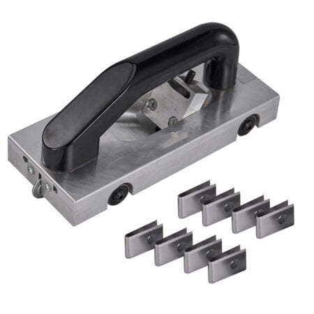
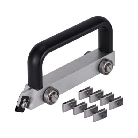


1. Identify the Groover and Blade System
Record the exact groover model, serial or revision, order reference and current blade marking. Separate the three electric groover families from the wheel-guided and plain hand tools. Photograph the installed arrangement before removal by the permitted procedure. A handle colour, body size or familiar disc shape is not a part reference. Keep the complete machine name and its manual revision in the record so the blade can be checked against a specific mounting system.
2. Isolate Before Looking at the Mount
For a powered groover, switch off, wait until all moving parts stop, unplug and follow the manual before accessing the blade. Use the prescribed holding or locking method and blade-handling equipment. Do not loosen a live or coasting blade. For hand tools, secure the tool and protect the cutting edge while examining the holder. If removal or identification is beyond the permitted operator maintenance, arrange qualified service. Photograph accessible details without dismantling unrelated parts.
3. Measure an Electric Disc at Defined Datums
Record outside diameter, central bore, body thickness, stated cutting width and profile, plus any locating holes, slots, spacers or offset. Measure from the manufacturer’s defined datums; distinguish blade-body thickness from the width cut by its teeth. Record units and legible markings beside the images. A worn blade’s measured cutting width may not represent its original specification. Do not enlarge a bore or improvise a washer stack. Obtain the specified part drawing when a dimension cannot be identified reliably.
4. Check Rotation, Rating and Guard Clearance
Use the exact machine instructions to check blade direction, permitted speed or rating, fixing and clearances. Confirm that the specified guard and guides can be restored. Where the manual calls for it, check free rotation mechanically while the tool remains isolated, then refit the cover before operation. Do not power a blade with its guard removed. A matching outer diameter does not establish the correct bore, seating, clearance or operating rating.
5. Record Hand-Blade Retention Separately
For a hand groover, record blade length, width, thickness, cutting profile and the position of holes, slots or locating features. Photograph how the blade seats, how much engages the holder and how the working edge is presented. Compare any fixing screw, clamp or depth-adjustment relationship. A plain handle and a wheeled holder may use different retention even if their blades look related. Do not sharpen away a locating feature or alter the blade to fit another holder.
6. Match the Groove to the Exact Floor
Retrieve the flooring maker’s required groove profile and depth for the exact construction and rod. Check whether its surface or aggregate needs a particular blade material. Keep material suitability separate from mounting fit: a disc may fit a machine but be wrong for a safety-floor surface. Set and inspect a representative coupon only after the mechanical pairing is approved. Measure the resulting groove, examine its cross-section and confirm that the required layers remain intact before working on the floor.
| Selection point | What to check |
|---|---|
| Mechanical fit | Confirm the approved mount |
| Material groove | Use the specified profile and depth |
| Trial result | Assess the actual seam |
A Disc Diameter Is Only One Check
Leister’s GROOVER instructions cover mounting, free rotation and refitting the guard. WOLFF’s manual specifies its own replacement blades. Retain the exact machine reference when checking the bore, fixing and groove profile.
7. Save the Pairing for Replacement Orders
Create a line item with groover model and revision, blade code, mounting drawing or measurements, floor product and accepted groove test. Separate confirmed dimensions from values estimated from photographs. Retain the old part label and written pairing confirmation where available. Send that information with the selected tools or Groover Blades, quantities and destination. For distributor replenishment, label blade stock by the approved host tool and application so an unmarked disc does not become an assumed universal spare.
Related Products and Guides
الأسئلة المتداولة
Will a disc of the same diameter fit?
Not necessarily. Bore, thickness, cutting profile, retention, rotation, rating and guard clearance also matter.
Can I use an electric-disc checklist for a hand blade?
Use its holder’s own retention and working geometry; the systems differ.
Does mounting fit prove the groove is right for the flooring?
No. Verify the exact material requirement and the resulting coupon groove separately.
What information do you need for a wholesale quotation?
Send the product names or models, configurations, quantities and delivery destination. You can include mixing buckets, spreaders, spiked rollers and shoes in the same enquiry. The applicable quantity tier, packing details and order conditions will be reviewed for the selected items.
Can you customize the logo or packaging?
Send your logo artwork, preferred placement, packaging requirements and estimated order quantity. ARIK will review the available options for the selected tools and confirm the sample requirements, order conditions and quotation before production.
Can I request samples before a bulk order?
Include the models and configurations you want to evaluate, the intended application and the delivery destination in your enquiry. Sample availability, cost and shipping arrangements need to be confirmed for the selected items before an order is placed.
احصل على عرض الأسعار الآن
- اتصل بنا للحصول على عرض الأسعار المخصص لك.
- وفّر أكثر مع أسعارنا المباشرة!
- أسعار جملة تنافسية.
- لا وسيط، صفقات أفضل.

