
A wheeled hand groover can look aligned at the start and still leave the seam during the cut. Before changing the blade setting or pressing harder, check how the guide, support wheels and your hand movement relate to the joint.
This guide focuses on the ARIK Version 1.0 wheeled manual groover: establishing its path, recognising tracking changes and deciding when to stop a trial pass.
To keep a wheeled vinyl floor groover on the seam, establish the guide reference before cutting, keep the wheel frame supported and feed in the specified direction with a controlled grip. Test on matching offcuts, then inspect centring and groove shape. Stop when the guide loses its reference.
The useful question is what changes just before the cut moves off line. The checks below help separate a guidance problem from a cutting-edge problem without using the installed floor as a test piece.
Understand what guides the Version 1.0 groover
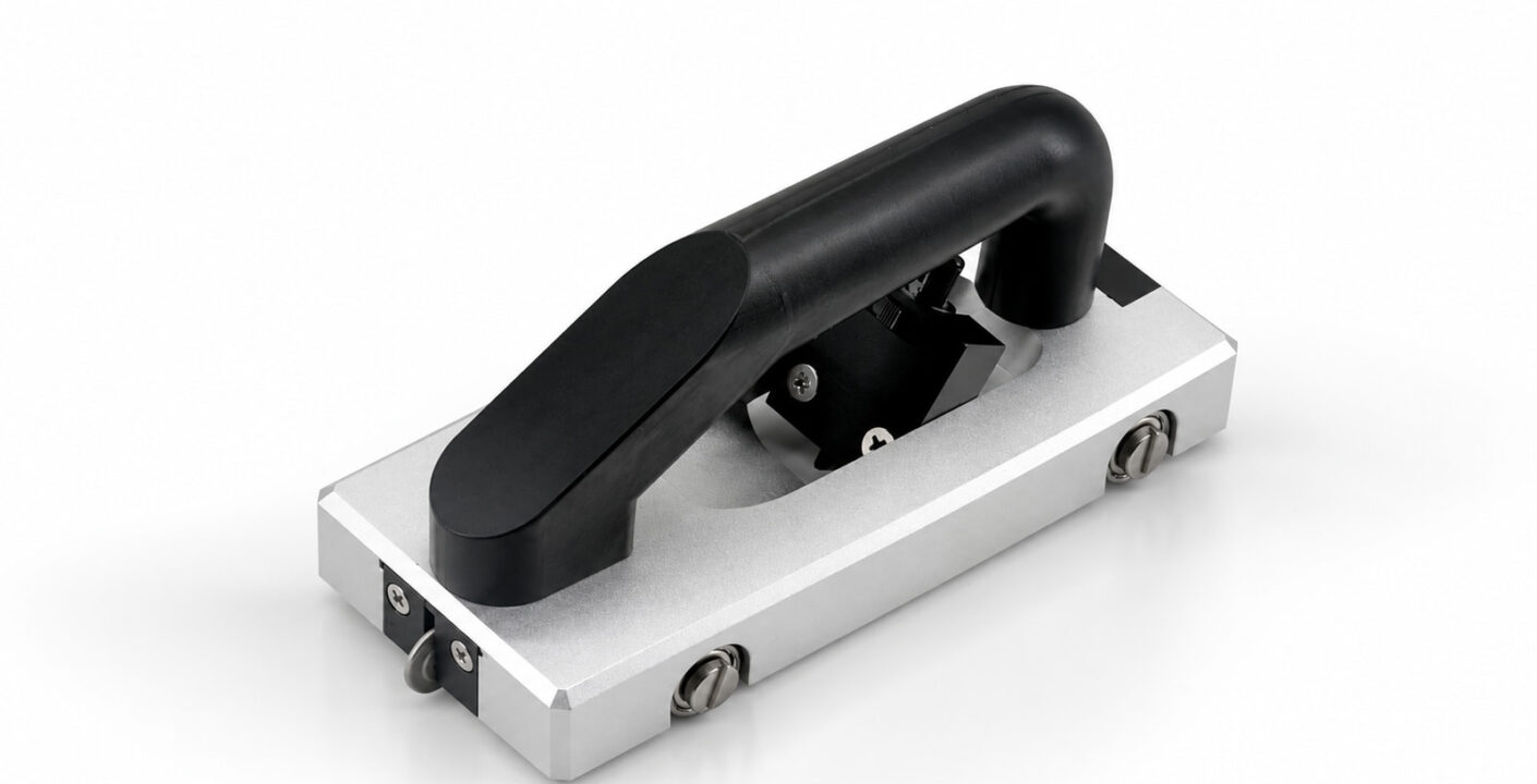
Die Version 1.0 wheeled floor groover uses hand feed and a cutting edge to form a seam groove. Its top grip and wheeled frame provide a way to support and position the tool. It has no motor driving the cut, and its wheels do not make it an automatic seam-following machine.
Before working, identify the cutting edge, the intended guide reference and the parts of the tool that support it on the flooring. Check their relationship on the actual assembled tool. A wheel that turns freely is one check; whether the guide can stay engaged with the intended seam reference throughout the stroke is another.
Keep three observations separate: the path of the tool, the position of the groove and the shape of the material removed. A straight-looking frame does not prove the groove is centred. Equally, a centred groove can have an unsuitable profile. Inspect the cut itself before accepting a setup.
Prepare a trial seam that can reveal tracking problems
Use matching flooring offcuts arranged as a representative joint. Support them securely so they do not shift as the tool moves, and provide enough flooring beneath the wheel frame for the intended pass. A narrow loose strip that cannot support the tool does not provide a useful comparison with an installed seam.
Identify the flooring product and its required joint preparation first. The permitted groove depends on the flooring construction and welding system. Altro’s published welding and grooving tips, for example, distinguish groove requirements between named flooring products. Those instructions illustrate why a single depth rule should not be applied to every sheet vinyl.
Use the current instructions for the material on your job, including when grooving is permitted and which layers must remain intact. This article does not set a universal blade projection, groove width or depth. The overall width of a tool is not its cutting width.
Clear chips and other obstructions from the trial route. Leave room for the tool, your hand and the full working stroke. Keep spare blades and measuring tools outside that route, and keep hands clear of the cutting path.
Check the blade and wheel frame before choosing a direction
Inspect the cutting edge, holder and fastening with the tool stationary and the edge handled safely. Confirm the blade belongs to the actual groover and is secured in the permitted arrangement. Do not assume that a similar-looking replacement blade has the correct mounting or cutting geometry.
Check the guide and support wheels for damage, obstruction or loose parts that prevent their intended movement. Inspect the surfaces that will contact the flooring. If a component cannot maintain its reference, correct that condition before attempting to compensate with your grip.
Choose the entry direction from the instructions for the actual tool and fitted cutting edge. A handle shape alone does not establish that a blade should be pushed or pulled. Do not reverse the tool under load simply because the opposite direction feels easier on the first attempt.
The wider work sequence, from material identification to finishing the seam, is covered in our guide to using floor groovers. Here, concentrate on whether the Version 1.0 frame and guide can remain in their intended positions along your trial joint.
Establish the guide before starting the cut
Position the tool at the trial seam’s entry and check the intended guide contact before engaging the cutting edge. Look at the seam reference and wheel support together. Starting with the frame partly unsupported makes it difficult to tell whether later deviation comes from the setup or the cutting action.
Check your starting posture as well as the tool position. You should be able to complete a manageable stroke without reaching around the frame or twisting the grip to keep sight of the seam. If the planned movement hides the reference or takes your hand into an awkward position, shorten the working section or reassess the approach on the offcut.
Begin with a short, controlled trial pass in the specified direction. Use the intended grip and keep the tool supported. Do not apply a sudden sideways correction while the edge is cutting to rescue a misplaced start. Stop, inspect the result and re-establish the setup on a fresh trial section.
A useful starting check is simple: can you identify the guide reference before the cut, maintain it during the stroke and see where the groove actually begins? If any part is unclear, resolve it before making a longer pass.
Watch the tool’s support throughout the stroke
Wheeled floor groover tracking depends on more than the starting position. Watch for a wheel losing contact, a guide leaving its reference, the frame meeting an obstruction or your hand pulling the grip sideways as your reach changes. These are observations to investigate, not reasons to increase pressure automatically.
Maintain a controlled feed rather than alternating between a light movement and a heavy shove. If resistance changes suddenly, stop the trial. Inspect the cutting edge, material, guide contact and support before deciding what to change. Forcing the tool through an unexplained change can damage the offcut and hide the original cause.
Keep working sections short enough to preserve your position and view. Reposition yourself before your reach becomes the main influence on the tool’s direction. Establish a restart method on the trial seam and inspect the transition rather than assuming separate strokes will produce a continuous acceptable groove.
If you are learning how to guide a wheeled vinyl floor groover, record where deviation starts: immediately at entry, after a posture change or at the same point along the route. That location gives you a more useful next check than the general description “the tool wanders.”
Separate tracking faults from groove-profile faults
After the pass, inspect the groove from above and inspect a suitable cross-section of the trial piece where needed. Compare the centring, sides, bottom and remaining flooring layers with the material requirement. The following observations help organise the diagnosis; they do not establish a cause without further checks.
The groove starts away from the seam centre
Review the entry setup first. Check the relationship between the guide reference and the cutting edge, the joint itself and the wheel support at the start. Repeat the trial only after that relationship is clear. Do not use a longer working pass to see whether an offset beginning will correct itself.
The groove begins correctly, then moves sideways
Note the first point of deviation. Inspect the route for an obstruction or support change and review whether your reach or grip changed there. On a fresh trial, keep the setup consistent and change one relevant factor at a time. This makes the result easier to interpret than changing the blade, feed and hand position together.
The groove stays centred but has torn or uneven sides
Do not treat every poor cut as a steering problem. Check the cutting-edge condition, blade fit, projection and suitability for that flooring. Compare the groove with the specified profile. A guide can follow the intended path while an unsuitable or damaged edge produces an unacceptable cut.
The groove reaches an unintended layer
Stop and review the blade setup against the exact flooring instructions. Wheel guidance does not verify cutting depth or protect the backing automatically. Do not continue on the installed seam on the basis that the line looks straight. Correct the setup and assess another representative trial piece.
Plan the point where the frame can no longer follow
Near a wall, doorway or other restriction, the frame may run out of clearance before the required groove ends. Assess that space before the working pass. The relevant clearance includes the support frame, grip and your hand, not just the position of the cutting edge.
Do not tilt the tool or deliberately lift a support wheel to extend its reach beyond the arrangement you tested. Identify where the wheeled pass must stop and evaluate a suitable detail tool for the remaining section. Inspect the transition so the groove does not change abruptly or leave an unprepared end.
If the restriction is part of the trial, reproduce it safely without placing your hand against the cutting path. Where the tool cannot stay supported and maintain its guide reference, that is a limit of the tested approach. A successful open-floor pass does not prove the same tool can finish every corner.
Compare Version 1.0 and 2.0 by the task
If the Version 1.0 frame does not suit the available space or your working position, the Version 2.0 wheeled floor groover offers a different, smaller body layout to evaluate. That size difference does not establish better tracking, a deeper cut or interchangeability of blades.
Compare the tools on matching seams with their verified blade arrangements. Record support, visibility, grip, entry and exit clearance, then inspect the grooves. Keep the material and acceptance requirement consistent. If the blades or settings differ, record those differences rather than attributing every result to tool size.
A heavier tool does not demonstrate constant hand pressure, and a lighter tool does not guarantee control in a restricted position. Choose from the actual working fit and accepted trial result. Version numbers describe the models; they are not a validated ranking of groove quality.
Keep a short record before moving to the installed floor
A useful trial record lets another installer understand what was tested and lets you recognise when conditions change. It need not be complicated:
- Identify the flooring, joint arrangement and applicable installation instructions.
- Record the groover model, blade identification and accepted setup.
- Note the feed direction, starting reference and support arrangement.
- Describe any tracking deviation, clearance limit or change in resistance.
- Photograph the groove, its ends and a relevant trial cross-section.
- Record which checks passed and what still needs correction.
Repeat the relevant trial when a change affects the setup, such as a different blade, flooring construction or access condition. Do not carry an accepted setting to a different task without checking what has changed.
Once guidance and groove quality are acceptable, place the operation back into the full seam process. Our overview of sheet vinyl welding tools explains how grooving connects with welding, trimming and inspection. Welding is a later step, not a way to conceal an unassessed groove defect.
Keep the reference, then judge the cut
Keeping a manual wheeled groover aligned starts with a supported frame, a clear guide reference and an entry direction appropriate to the fitted blade. Controlled movement helps you maintain that setup; inspection of the trial groove tells you whether it achieved the required result.
For help evaluating the Version 1.0 model, send ARIK the flooring identification, seam layout, blade details and photographs of the trial groove and restricted areas. Those details support a useful discussion of tool fit and configuration before you commit to the working seam.
