
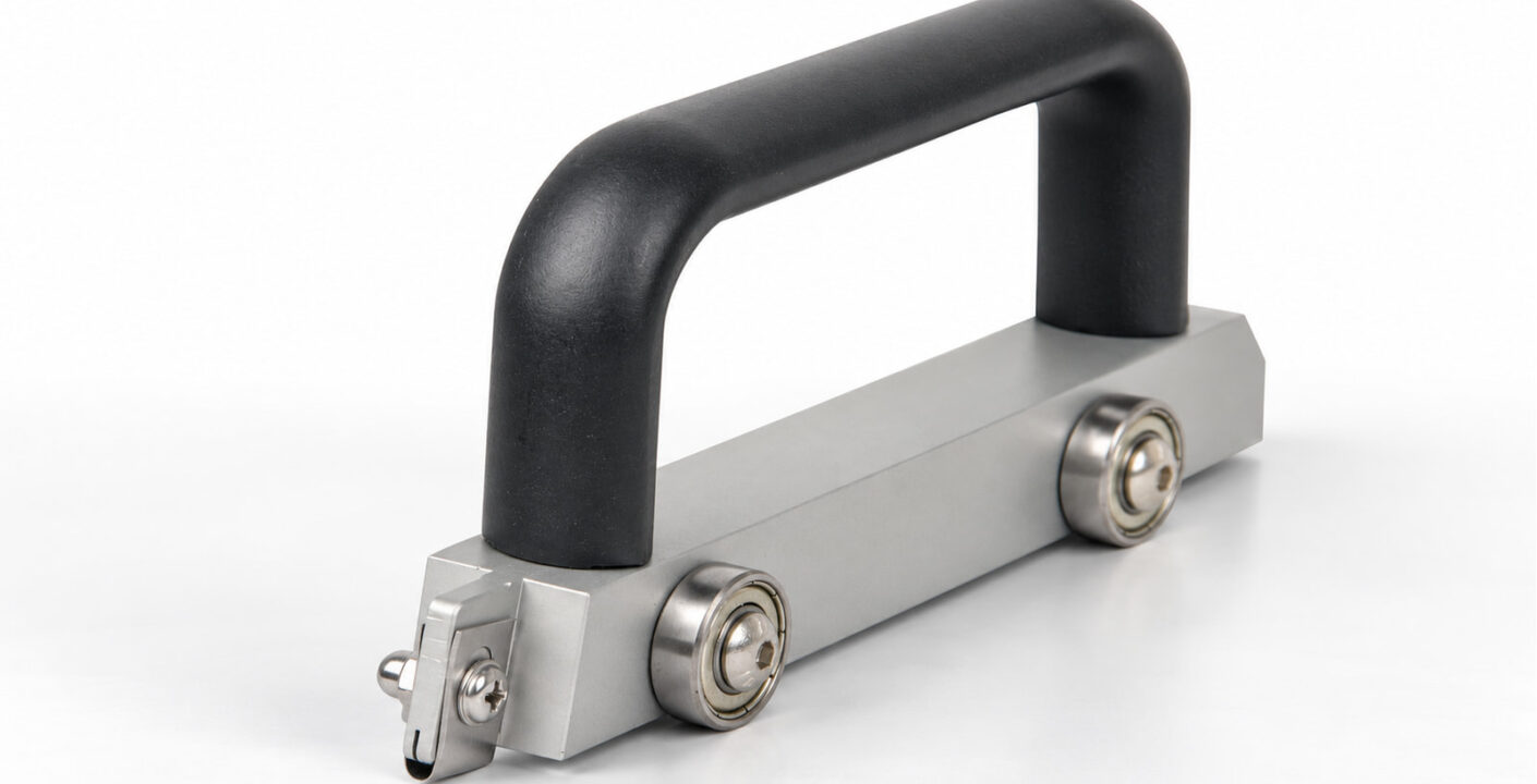
A floor groover can look small enough for a wall-side seam and still leave no room for the operator’s hand, the wheel frame or the cutting head. For a commercial flooring crew, that becomes a selection problem before it becomes a cutting problem. The useful question is whether the complete working arrangement can enter, follow and leave the intended seam while producing the required groove.
Choose a compact manual floor groover for tight spaces by checking the tool, hand and cutting path together. Confirm wheel support, entry and exit clearance, then test the groove on matching flooring. A narrow body alone does not establish wall clearance or suitable cutting depth.
The checks below help a crew leader decide whether a smaller wheeled tool belongs in the working kit, where it can be used and where another arrangement needs assessment.
Start With the Restricted Part of the Seam
Identify what makes the work area tight. A wall alongside a straight seam creates a different restriction from a short seam ending at a door frame. An internal corner can block forward travel, while a coved floor detail can change the surface supporting the wheels. These positions should be assessed individually.
Before selecting a tool, record the seam direction, the nearby obstruction and the part of the flooring that must be prepared. Check the flooring manufacturer’s requirements for that material and joint. Establish whether the detail requires grooving and what groove profile it needs before choosing the cutting arrangement.
A useful site note describes the restriction directly: the grip approaches the wall, the front of the tool reaches the frame before the cutting edge finishes, or the wheel frame loses support near the transition. That gives the supplier and installer a clearer problem to solve than the description “small corner.”
Read Overall Dimensions as a First Screening Check
The current listed overall dimensions of ARIK’s version 2.0 wheeled floor groover are 155 × 40 × 72 mm, with a net tool weight of 0.3 kg. These figures provide a starting point for comparing the complete tool’s size and carrying load.
They do not describe a 40 mm groove, a 40 mm minimum wall distance or a guaranteed working envelope. The cutting edge’s position relative to the frame, the available hand space and the direction of travel all affect actual access. Check the supplied configuration when precise clearance matters.
Use length to screen a short entry or stopping area, width to screen the space beside the seam, and height to screen restrictions above the body. Then inspect the tool in the intended working position. A drawing or dimension list can eliminate an obviously unsuitable option, but a borderline fit needs a physical check.
Keep product size separate from blade specifications. Overall dimensions cannot confirm groove depth, groove width, blade mounting or interchangeability with another brand. Obtain the relevant cutting-head information and verify the groove independently.
Check the Hand, Wheel Frame and Cutting Head Together
Allow Space for the Working Grip
Place the tool beside a representative obstruction and check the grip the installer will actually use. Include the normal gloves and working posture. The operator should be able to hold and guide the tool through the intended movement without relying on an awkward grip that only works while the tool is stationary.
Watch what happens as the hand approaches the wall or frame. If the operator must change grip halfway through a short run, include that change in the trial. A smaller body can improve the available room, but grip suitability still needs to be demonstrated by the person doing the work.
Preserve the Intended Wheel Support
Inspect where the wheels and frame will sit throughout the travel. A body that passes the obstruction may still leave a wheel unsupported or bring the frame into contact with a raised detail. Check the complete path rather than one convenient position at the middle of the seam.
For a wall transition, reproduce the change in surface or support in the mockup. Do not assume a tool intended to travel along a supported seam can retain the same working arrangement over a curve or abrupt change in plane. If the required support is unavailable, reassess the tool and sequence before cutting.
Locate the Cutting Edge Within the Available Space
Establish how close the cutting edge can reach to the start and end of the intended groove while the frame remains correctly positioned. The front of the body may encounter an obstruction before the edge reaches the required endpoint. A narrow body can therefore pass a side-clearance check and still fail an end-access check.
Inspect blade condition, mounting and clearance according to the tool’s instructions. Keep hands away from the cutting path, and use a controlled trial arrangement. Do not loosen or alter a blade mounting to make an otherwise unsuitable tool reach an obstruction.
Rehearse Entry, Travel and Exit Before Cutting the Installed Floor
Use matching flooring offcuts and a representative wall, frame or corner arrangement to check access. Start by observing the planned movement without making a cut, using a safe setup appropriate to the tool. Then make a trial groove after the cutting arrangement and material requirements have been confirmed.
- Entry: Check that the complete tool and grip can reach the starting position with the intended wheel support.
- Travel: Follow the seam direction and look for contact between the hand, frame, cutting head and obstruction.
- Exit: Check how the groove will finish and how the tool can be withdrawn without an uncontrolled movement.
- Result: Inspect the trial groove against the flooring system’s specified profile and preparation requirements.
Repeat the trial in the actual direction required on site. Reversing a mockup merely to make access easier does not establish that the proposed method fits the installed detail. Likewise, a successful trial beside a flat board does not validate a corner with a different radius or support arrangement.
If the tool stops short, record where and why. Separate a frame collision from a grip restriction or loss of guidance. Each calls for a different decision. Stop and reassess rather than forcing the tool through a position that has already failed the access check.
Compare 1.0 and 2.0 Under the Same Conditions
The current listed dimensions of the version 1.0 wheeled floor groover are 205 × 83 × 90 mm, with a net weight of 1.2 kg. Against those figures, the 2.0 body is 50 mm shorter, 43 mm narrower and 18 mm lower, and its net weight is 0.9 kg less.
Those differences explain why 2.0 is worth assessing where the larger body or grip arrangement restricts access. They do not establish that 2.0 cuts deeper, follows a seam more accurately or replaces the larger tool in every position. Version numbers identify the options; the trial establishes their suitability for the task.
Compare the tools on the same flooring, joint detail and obstruction layout. Confirm each tool’s fitted blade and setup before evaluating it. Record access, grip control, wheel support and the resulting groove separately. Otherwise, an unsuitable blade or a different material can be mistaken for a body-size effect.
If both arrangements fit and produce the required groove, consider the installer’s grip preference and the working sequence. If only the smaller arrangement fits, it still has to pass the groove check. If neither fits, the next step is to assess another cutting-head layout or work method.
Treat Coving and Corners as Complete Details
Work near a cove can involve marking, cutting, forming, pressing, joint preparation and trimming. Choosing a compact groover addresses only the relevant grooving operation. It does not resolve the whole detail or establish that every corner must be grooved in the same way.
Review the seam location and construction using the vinyl floor coving tools and corner workflow as a planning reference. Follow the flooring system’s instructions for the actual construction. Check internal and external corners separately, since the tool’s approach and the surrounding surfaces differ.
A compact wheel frame may be a candidate for one accessible section while another section requires a different arrangement. Mark that boundary in the mockup. Confirm how adjoining prepared sections will meet, and inspect the changeover area before accepting the method for production work.
Do not use a successful groove on a flat sample as proof of access on an upright or curved detail. Build the relevant geometry into the trial and check the complete working posture. Where a wheel frame cannot maintain its intended support, assess a suitable alternative rather than assuming reduced body width solves the problem.
Accept the Groove Separately From the Fit
Access is the first gate. The resulting groove is the second. A tool that clears the wall can still produce a groove that does not match the flooring system’s requirements. Check the profile at the start, middle and end of the trial, including any area where grip or support changes.
Use the flooring manufacturer’s method and acceptance criteria for the material, thickness and joint. Do not adopt a universal depth from the groover’s body dimensions or from a different flooring product. Confirm blade geometry and the permitted setup before trying to correct a poor result.
For a crew handover, keep a simple record of the tool version, fitted blade, material, obstruction layout and trial outcome. A photograph showing the hand and wheel frame is useful for explaining access; a separate view or measurement of the groove documents the cutting result. Label these as site checks for that arrangement.
Keep Portability and Spare Parts in the Selection Decision
The 2.0 model’s listed 0.3 kg net weight is relevant when assembling a personal tool kit or moving between scattered work positions. Compare the complete kit that the installer needs, including any other tools required to finish restricted sections.
Lower tool weight does not by itself establish lower operating effort or greater control. Material resistance, the cutting edge and the working grip also need assessment. A selection that saves carrying weight still needs a satisfactory trial in the intended posture.
Before ordering, confirm the supplied blade, replacement part identification and included components. Similar appearance is insufficient evidence that another brand’s blade will fit. Keep shipping and packaging information separate from the net tool weight when planning transport.
Make the Decision With a Short Acceptance Checklist
For each restricted work position, confirm these five points before assigning the tool to the crew:
- The material and joint require the proposed preparation method.
- The hand, wheel frame and cutting head fit throughout entry, travel and exit.
- The tool retains its intended support and guidance.
- A representative trial produces the required groove profile.
- The blade configuration and any changeover to another tool are understood.
Choose the compact arrangement when it passes all five checks for the intended position. Reassess it when a restriction, blade or material changes. This gives the crew a specific working decision instead of a general claim that a small groover suits every tight area.
For the broader choice between powered, guided manual and plain hand tools, see how to choose a floor groover. To discuss a restricted position with ARIK, provide the flooring details, required groove, obstruction measurements and photographs showing the proposed approach. That information helps confirm which configuration to assess before committing to the installed seam.
