
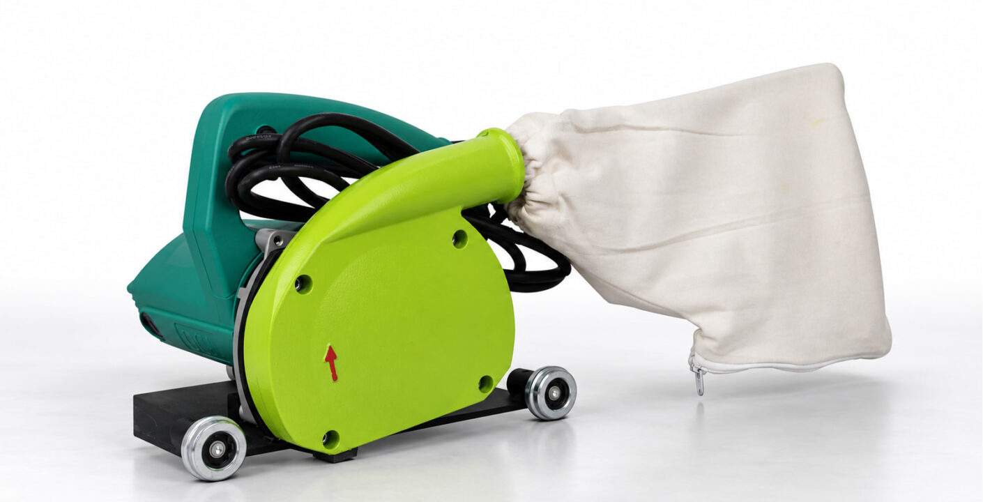
A floor groover may offer a wide adjustment range, but the seam needs a setting matched to the flooring being installed. For commercial flooring crews, the useful question is how to turn the specified groove profile into a checked, repeatable setup.
How deep should you groove vinyl flooring for heat welding?
Set vinyl floor grooving depth for heat welding from the instructions for the exact flooring and approved weld rod. Check the specified profile on a representative offcut before proceeding. A groover’s adjustment range describes the machine; it does not prescribe the correct depth for every floor.
The checks below help you separate the material requirement, blade configuration and trial result, then record a setup that the crew can identify.
Start with the flooring construction and its installation instructions
Identify the actual floor covering before adjusting the tool. A description such as “commercial PVC sheet” is useful for locating a product family, but it does not identify every layer, backing or seam requirement within that family.
Have the following information available at the work area:
- The flooring manufacturer, product name and construction.
- The specified thickness and any backing relevant to the groove.
- The approved welding rod, including its identity and diameter.
- The required groove shape, width and depth, or the construction layer that defines the depth.
- The seam-preparation method and required adhesive-curing conditions.
Read these items together. A groove-depth figure separated from its product instructions can lose the condition that makes it applicable. If a requirement refers to a particular layer, identify that layer in the actual flooring rather than converting the instruction into a percentage of overall thickness.
If the product cannot be identified or the grooving instruction is unclear, resolve that point with the flooring supplier before using the finished seam as the test piece. The next useful step is a defined requirement, followed by a representative trial.
Is the two-thirds rule suitable for every vinyl floor?
Manufacturer guidance illustrates why construction matters. Gerflor’s Heat Welding Vinyl Products instructions, dated June 18, 2024, distinguish these cases for the products covered by that document:
| Floor construction in that guide | Grooving-depth instruction |
|---|---|
| Homogeneous flooring | Two-thirds of the total thickness. |
| Compact heterogeneous flooring | Two-thirds of the total thickness. |
| Heterogeneous flooring with comfort backing, or sports flooring | Reach the top of the foam without grooving into it. |
These are product-specific examples, not an ARIK setting chart for every vinyl covering. Obtain the current instructions for the named product on your project and use the construction definition given there.
Tarkett’s Homogeneous Sheet Vinyl Heat Welding Guide also gives a thickness-based instruction for its covered system and stresses alignment across both sheets. Keep that product scope attached to the instruction when preparing a crew briefing.
Separate the machine’s range from the required groove
ARIK lists a groove-width range of 2–5mm and a depth-adjustment range of 0–4.5mm for the green 1200W electric floor groover. Those figures describe the machine’s range. They do not tell you to use the deepest setting or establish a suitable groove for a particular flooring product.
Use three separate entries in the setup record: the flooring requirement, the selected machine setting and the measured trial groove. Keeping them separate makes a discrepancy easier to investigate. A setting that appears plausible on the control still needs to produce the required result in the actual material.
Also separate blade outline, blade projection and finished groove dimensions. They describe different things. The machine model and a number on an adjustment mechanism cannot replace checking what the cutting edge produces along the seam.
Check the blade and guidance before changing the depth
Confirm the blade configuration for the selected machine. Relevant checks include the blade’s outside diameter, bore, thickness, cutting profile, mounting and part identity. Use the floor groover blade compatibility guide to organise those checks.
A matching colour, wattage or broadly similar blade shape does not establish interchangeability. Likewise, confirming that a blade mounts to the tool does not establish that its cutting profile matches the flooring system’s required groove.
Inspect the guide wheels, depth adjustment, locking arrangement and chip-collection connection. Follow the machine’s instructions for setup, engagement, withdrawal and maintenance. Disconnect the power supply before fitting or changing the blade.
If the trial result varies, review the complete setup before making repeated depth changes. Blade condition, guidance and the way the sample is supported belong in that review. Record what was changed so the next trial can be compared meaningfully.
Make and inspect a representative trial groove
A trial should represent the seam you intend to prepare. A loose piece of different flooring may be convenient, but it cannot establish the result for the specified construction and installation conditions.
- Identify the sample. Use offcuts from the target flooring and retain the product information. Keep the relevant weld-rod and groove requirements beside the sample so the intended result remains clear.
- Prepare stable support. Set up the trial in conditions representative of the installation, including the applicable adhesive application and curing requirements. Avoid treating an unsupported offcut as equivalent to the installed floor.
- Inspect the tool. Check the blade identity and condition, guidance, depth setting and locking arrangement. Confirm that the selected tool can enter and leave the trial area as its instructions require.
- Make a controlled pass. Follow the required groove profile and the machine’s operating procedure. Keep the sample, blade and operating method identifiable rather than changing several variables without a record.
- Check the groove geometry. Assess width and depth at representative positions along the pass using the specified inspection method. Compare the actual groove with the flooring requirement, including any relevant construction layer.
- Inspect the surrounding material. Look for tracking deviation, chipped seam edges and damage to backing or underlying layers. A depth measurement is only one part of reviewing the prepared seam.
- Validate the next operation. Use the required trial-welding and inspection procedure for the system. Record the acceptable configuration before transferring the setup to the working seam.
Keep the trial piece or a clear record of its identity and observations where practical. It gives the crew a reference for the result that was checked, rather than leaving only an unexplained setting written on a note.
Check access at seam ends before starting the long run
A successful straight trial does not show how the same tool will reach a wall, doorway or other restricted position. Walk the intended seam before production and identify where the powered groover can operate with the required support and guidance.
Plan a suitable finishing method for sections the machine cannot reach. The green electric model is intended for seam grooving; its use does not establish flush-to-wall access. Where a separate manual grooving tool is needed, match its cutting profile to the flooring requirement and check the transition between the two prepared sections.
Include that transition in the trial when it forms part of the job. Compare the groove along the powered section, the manually finished section and their meeting point. Record any change in tool, blade or method so the installer completing the end knows which configuration was checked.
This access review also makes the setup more useful for a crew leader. It identifies who will prepare the long seam, who will finish restricted areas and which sample demonstrates the intended result. Agree on those responsibilities before welding starts, while the groove is still available for inspection.
What should the crew recheck when the groove looks wrong?
Use the observations to decide what to review. The following checks are an investigation aid, not a diagnosis of every possible defect.
| Trial observation | Checks before continuing |
|---|---|
| The groove is off the intended seam line. | Review seam alignment, guide-wheel support, entry direction and tracking along the pass. |
| Depth changes along the trial. | Recheck sample support, depth locking, blade condition and the recorded operating method. |
| Backing or an underlying layer is damaged. | Stop and compare the cut with the specified construction layer, depth and blade configuration. |
| The width or profile differs from the requirement. | Reconfirm the blade profile, mounting and actual groove measurements against the material instructions. |
| The groove looks acceptable, but the trial weld raises concerns. | Review the system’s welding and inspection requirements separately; groove appearance alone does not verify the completed weld. |
After an adjustment, make another representative trial and record the result. Do not hide a discrepancy by changing the acceptance description to match the groove already produced.
Record the setup so another installer can identify it
A useful handover connects the flooring requirement to the tool and the checked sample. “Use the same setting as yesterday” leaves out information the next installer needs to confirm.
Include these items in the job record:
- Flooring product, construction and the installation-instruction reference.
- Weld-rod identity and the required groove profile.
- Groover model and the actual blade configuration.
- Selected depth setting and measured trial width and depth.
- Sample support, adhesive-curing conditions and operating method.
- Observed edge condition, backing condition and tracking.
- Trial-weld inspection outcome, responsible installer and any unresolved item.
If the required profile or working position calls for a different tool, compare vinyl floor groovers by their actual blade, guidance and access requirements. Validate the selected configuration at the intended position; a powered blade or a larger tool body does not by itself prove a suitable result.
Keep groove preparation connected to the welding process
Depth, width and alignment prepare the joint for the next operation. The complete workflow also includes the selected rod, welding equipment, material-specific settings, trimming and the required inspection.
The sheet vinyl welding tools application page shows how those tool roles fit together. Use it to organise the workflow while retaining the flooring manufacturer’s instructions for the actual installation.
A smooth-looking final surface does not independently establish weld integrity. Keep appearance observations separate from the acceptance checks specified for the installed system.
Frequently asked questions
Can I simply use the groover’s maximum depth?
No. The maximum adjustment describes the tool’s range. Start with the instructions for the named covering and rod, then check the selected setup on representative material. If the required groove cannot be produced with the proposed configuration, resolve the blade, tool or material requirement before proceeding.
Is matching groove depth enough to approve a seam?
No. Review groove width, profile, alignment and adjacent-material condition as well. The welding and inspection stages also need their own checks. A depth reading or a flush finish cannot, on its own, establish that the complete seam meets the flooring system’s acceptance requirements.
Can the crew reuse a checked setting on another flooring product?
Recheck the requirement when the flooring, construction, rod, blade or installation setup changes. Retain the earlier record as a reference, but confirm that it applies to the new task. Where the material instructions leave a question unresolved, obtain clarification and make the appropriate trial before using the working seam.
Before the first production seam
Confirm the material instruction, match the blade, inspect a representative groove and retain the checked setup. That sequence gives the crew a practical basis for controlling vinyl floor grooving depth for heat welding.
For help checking an ARIK groover configuration, provide the flooring product and construction, required groove profile, weld-rod details and site power supply. This gives the tool discussion a defined installation requirement to work from.
